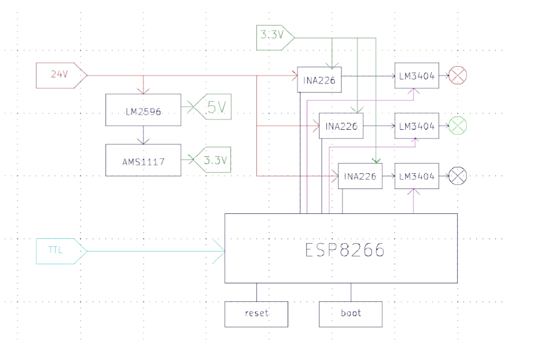
This project implements a high-power RGB LED lighting system controlled via WiFi. The lamp uses three 5W LEDs, each regulated by a dedicated LM3404 LED driver and monitored by an INA226 current sensor. An ESP8266 (ESP-12E) microcontroller manages wireless control and power monitoring through a web interface.
Designed as part of a 2024–2025 power electronics curriculum, the project emphasizes practical hardware design, power regulation, thermal analysis, and embedded software integration.
https://git.schoonbaert.net
You cannot select more than 25 topics
Topics must start with a letter or number, can include dashes ('-') and can be up to 35 characters long.
|
|
1 year ago | |
|---|---|---|
| PowerRGB | 1 year ago | |
| PowerRGB-backups | 1 year ago | |
| assets | 1 year ago | |
| blok-power-RGB | 1 year ago | |
| LM3404MA_2.kicad_sym | 1 year ago | |
| PowerRGB.kicad_pcb | 1 year ago | |
| PowerRGB.kicad_prl | 1 year ago | |
| PowerRGB.kicad_pro | 1 year ago | |
| PowerRGB.kicad_sch | 1 year ago | |
| PowerRGB.zip | 1 year ago | |
| PowerRGB_2.kicad_pcb | 1 year ago | |
| PowerRGB_2.kicad_prl | 1 year ago | |
| PowerRGB_2.kicad_pro | 1 year ago | |
| PowerRGB_master.ino | 1 year ago | |
| PowerRGB_standalone.ino | 1 year ago | |
| README.md | 1 year ago | |
| fp-info-cache | 1 year ago | |
| schematic.pdf | 1 year ago | |
README.md
WiFi-Controlled RGB Power Lamp
This repository documents the design and implementation of a WiFi-controlled RGB lamp using discrete power electronics and embedded systems. The lamp is based on 3× 5W LEDs (RGB), driven by LM3404 constant-current drivers, monitored by INA226 current sensors, and controlled by an ESP8266 microcontroller via a custom web interface.
Overview
- Microcontroller: ESP8266 (ESP-12E)
- LED Drivers: LM3404, one per color channel
- Current Sensors: INA226 (I²C), one per channel
- Power Supply: 24V DC input, regulated to 5V and 3.3V
- User Interface: Web application hosted on ESP8266 for RGB control and power monitoring
System Architecture
Block Diagram:
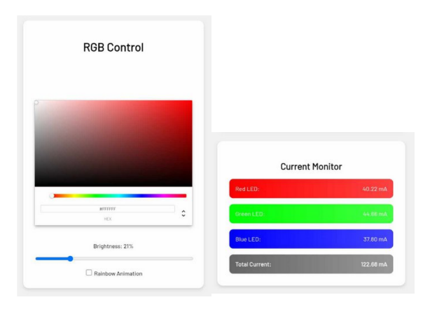
Web Interface
- RGB control using Vue-based color picker
- Adjustable brightness slider (mapped to PWM)
- Real-time current monitoring (INA226)
- Basic animation mode (rainbow sequence)
Web UI Screenshot:
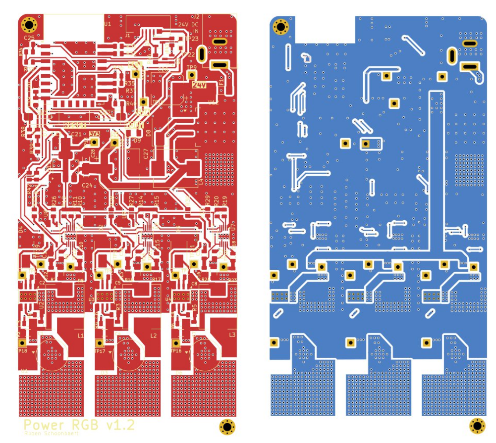
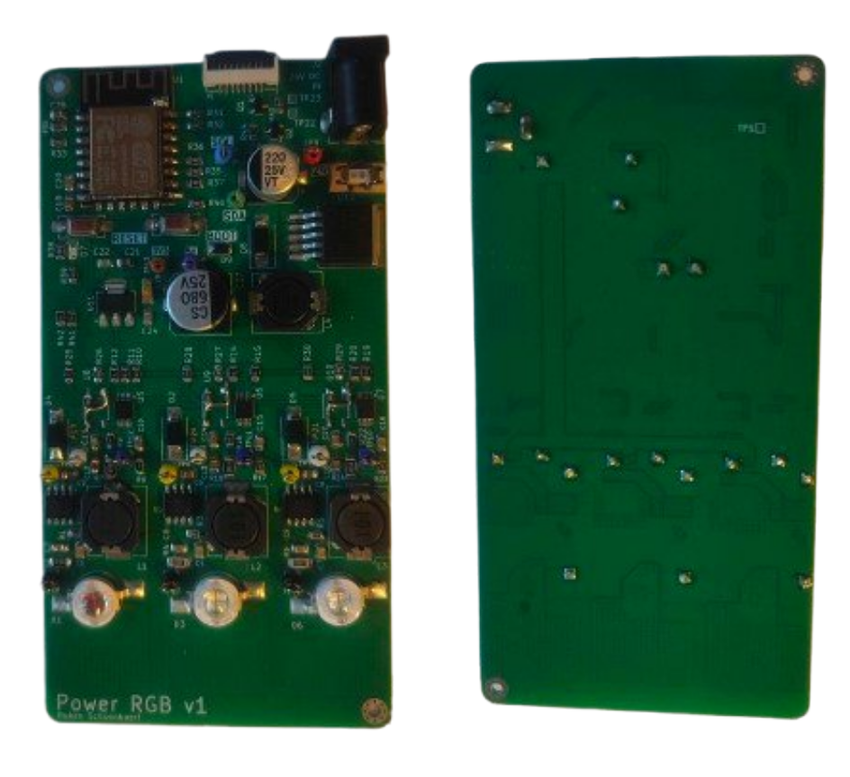
PCB Design
- 2-layer FR4 PCB with thermal copper pours and via stitching
- Test points for PWM, switch nodes, and sense lines
- FFC interface for external programmer
- Custom CH340C programming board (USB → UART)
gerber View:
3D Render:
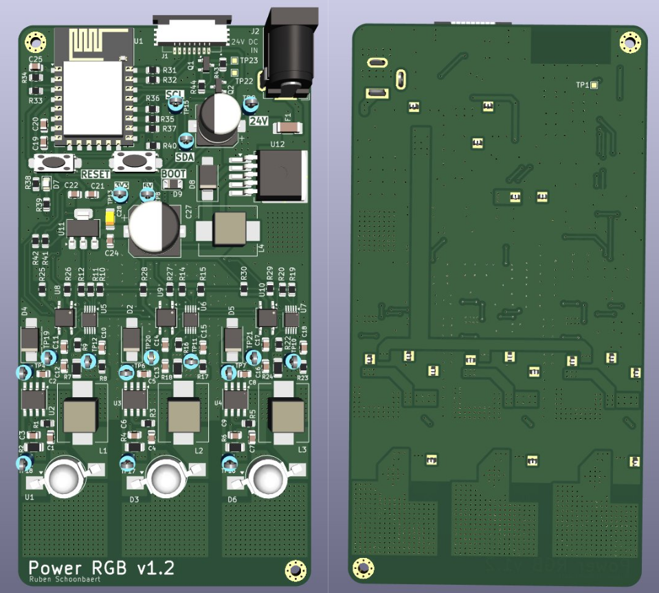
3D Render:
Testing and Analysis
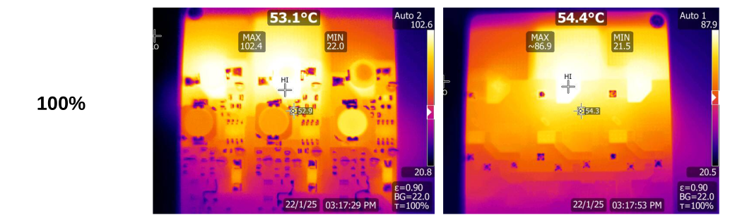
Thermal Imaging
- Thermal images captured using Fluke thermal camera
- Red LED remains coolest; green and blue require better cooling
- Thermal deviation from calculated values due to PCB/slug bonding
Thermal Measurement Example:
Oscilloscope Measurements
- Switching ripple observed and confirmed within expected range
- DCM ringing noted at switch nodes; no impact on operation
Known Issues & Improvements
- DIM Pin Fix: Initial circuit caused full brightness during MCU boot. Fixed with pulldown resistor.
- I²C Line Reversal: SDA/SCL reversed in layout; resolved via software GPIO reassignment.
- Thermal Solution: Future revisions should consider external heatsink or aluminum-core PCB.
Full Report
All design calculations, schematics, measurements, and references are available in the final report:
📄 Project_RubenSchoonbaert.pdf